
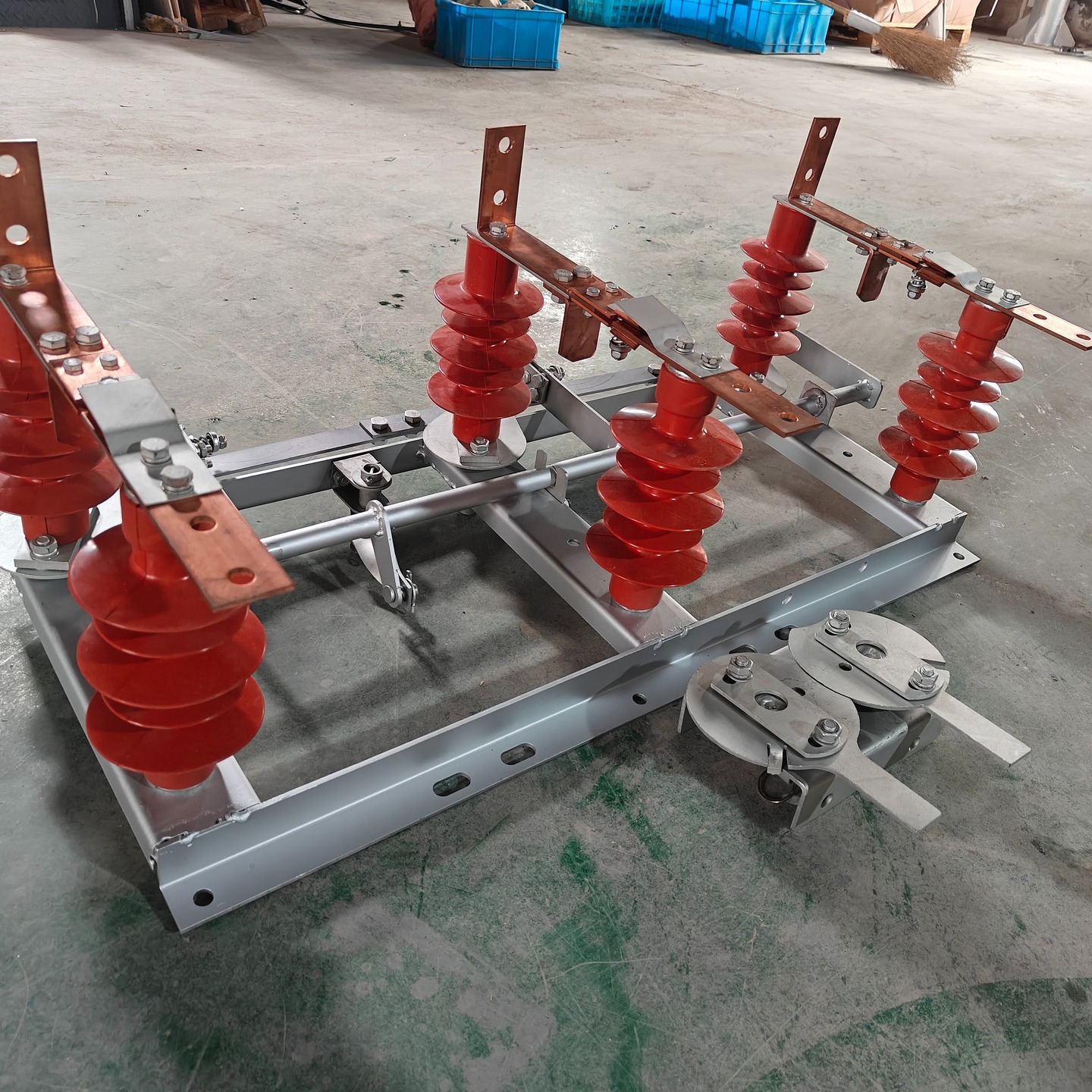
Designed to create a visible break in the electrical circuit in order to ensure safe servicing of electrical equipment;
The PRNZ-10 drive is designed for manual switching on and off of the main and grounding knives of disconnectors.
Disconnector RLND-1-10-200 U1, RLND-1-10-400 U1, RLND-1-10-630 U1
Disconnector RLND-10-200 U1, RLND-10-400 U1, RLND-10-630 U1
| Parameter name | Parameter value for disconnector types | ||
|---|---|---|---|
| RLND-1-10-200 U1 | RLND-1-10-400 U1 | RLND-1-10-630 U1 | |
| Nominal voltage, kV | 10 | ||
| Maximum working voltage, kV | 12 | ||
| Rated current, A | 200 | 400 | 630 |
| Electrodynamic withstand current, kA | 25 | 25 | 25 |
| Thermal withstand current, kA | 10 | 10 | 10 |
| Time of thermal withstand current flow, s: – for main blades – for grounding blades |
4 1 |
||
| Established resource for mechanical strength, cycles of VO | 10,000 | ||
| Leakage path length of external insulation, cm, not less than | 30 | ||
| Permissible tension of wires applied to fixed insulators, N, no more than | 200 | ||
| Material of support insulators | Polymer insulators | Polymer insulators | Polymer insulators |
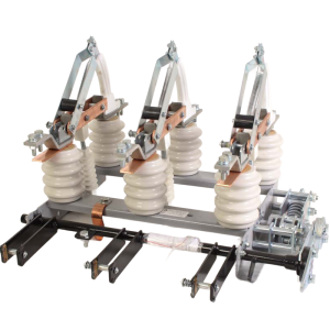
The disconnector is a two-pole or three-pole device, each pole of which has one fixed and one movable column, with the main knives turning in the horizontal plane.
The disconnector drive is designed so that it excludes the possibility of operating the grounding switch until the knives of the main circuit are disconnected. The drive body has openings for installing a block lock.
The isolation switch insulation consists of four or six insulators, two or three of which are mounted on levers and the rest on channels.
The current-carrying system, made in the form of two contact blades, is installed on the upper flanges of the disconnector insulators. The general appearance, overall, installation and connection dimensions of the disconnectors are shown in Fig. 1.
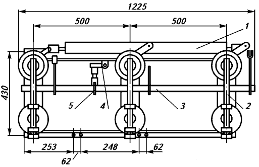
Designations: 1 – longitudinal rod; 2 – frame; 3 – ground shaft; 4 – lever with shaft; 5 – adjustable rod;
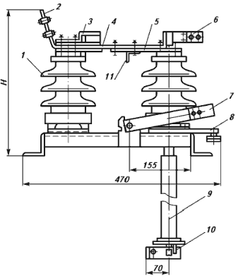
Designations:
Designations:
1 – insulator;
2, 6 – contact terminals;
3 – visor;
4 – contact blade;
5, 12 – detachable contacts;
7 – earthing conductor;
8 – lever;
9 – pipe;
10 – block lock;
11 – earthing conductor contact
Note. The pipe is not included in the factory delivery!




 Thai
Thai  English
  Russian
  Spanish
  Portuguese
  Vietnamese
  Arabic
  Indonesian